Custom Prius C Foglights (with factory wiring on trim level 2!)
With my new Prius C (trim II) I decided I wanted foglights that were only offered as an option on the next trim level up.
I asked the dealership and they wanted over $700 just for parts, before labor.
I decided I would attempt to create foglights that would operate like stock foglights but be brighter and more awesome using high power LEDs.With my new Prius C (trim II) I decided I wanted foglights, but there were only offered as an option on the next trim level up. I asked the dealership and they wanted over $700 just for parts, before labor. With further reading I was further discouraged to learn so called computer incompatibilities with trim level 2. I decided I would attempt to create foglights that would operate like stock foglights but be brighter and more awesome using high power LEDs. I decided I would investigate the electrical system and see if I could figure out how much was built into the wiring and if I could use any of it.
In the end I was pretty happy with what I came up with.
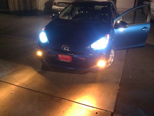
Results
These arn't the greatest photos, taken with my blurry cell phone.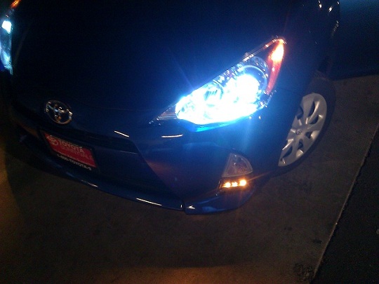
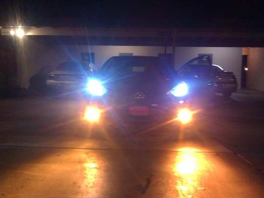 See the light turn off with the blinker
How to do it (or how I did it)
To begin with, you should view these links:Toyota of mcdonough prius C foglight kit This provides a nice set of parts, and instructions to install halogen foglights.
Prius Chat Foglight Thread Without this forum thread and the helpful people on it, I would not have been able to do this.
Schematics:
Schematic 1 . Schematic 2Wiring:
I actually started this halfway through my project, but it's useful to start here. Those who purchase factory parts, or other kits may find this particularly useful. You DO NOT need a wiring harness, fuses, or relays. You will need a switch of some kind, and some wiring, with some basic skills with wiring and soldering.
Finding the factory wiring harness:
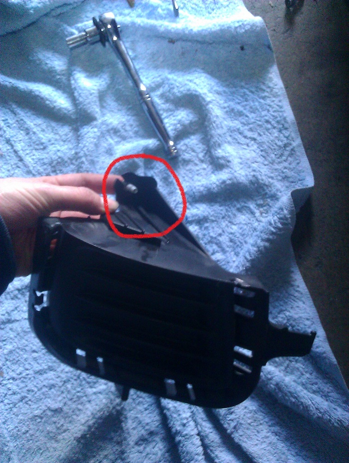
I took off the foglight cover and noticed the connector taped to the turn signal cable. I was unable to visually find where this cable went, but I determined ground was provided on one pin.Remove the foglight covers. You can use the Toyota of McDonough instructions make sure to remove the bolt (red) before ripping out the foglight cover
Tracing the wiring
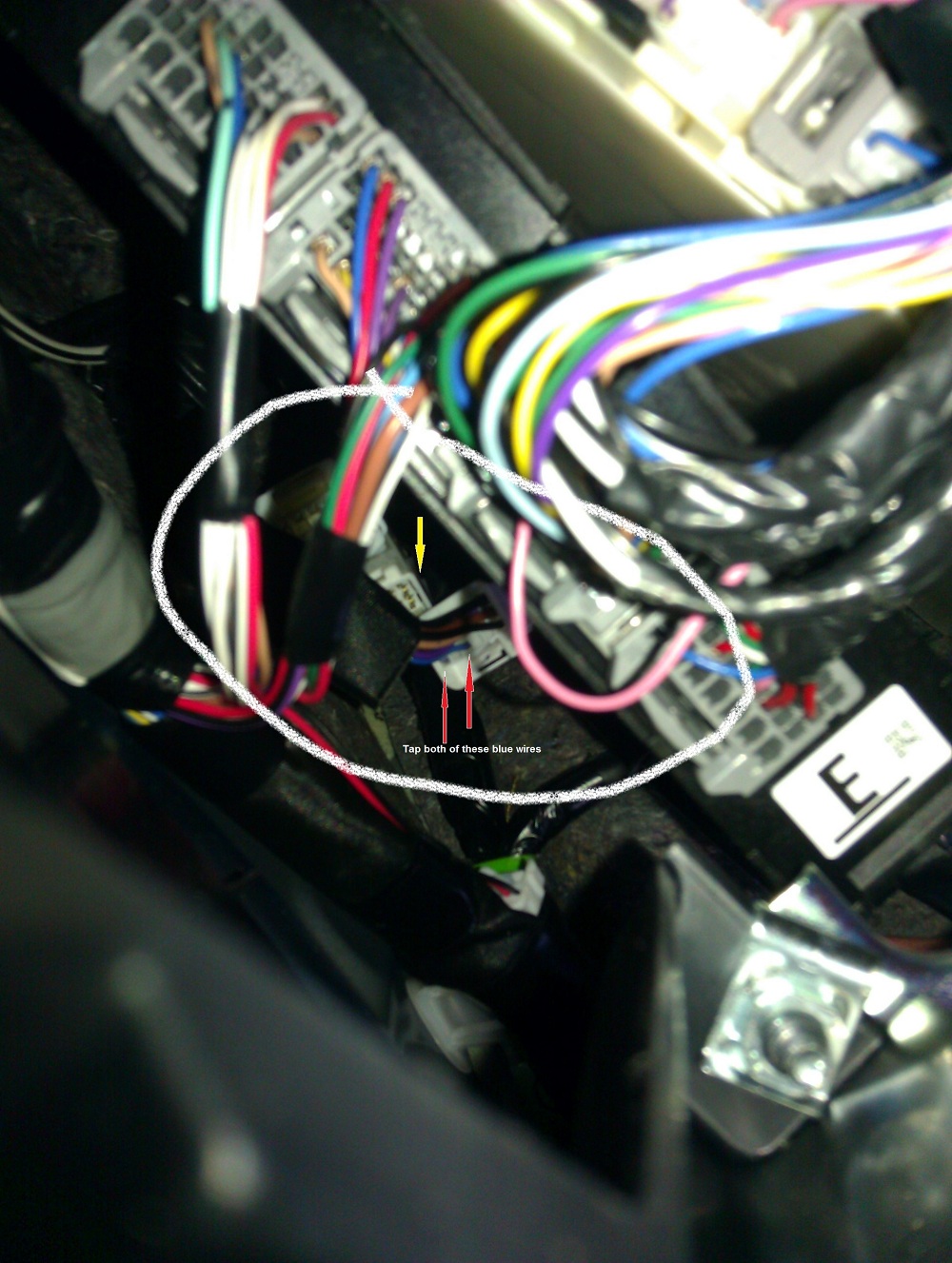
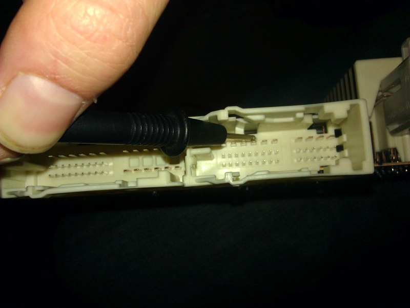
I couldn't find any diagrams to where the factory harness went, so I went out and bought a wire tracer ($70). I found the wire to come into the car near the interior fuse box.Disconnect the connector pointed to with the yellow arrow. Tap the two wires pointed to with red arrows. Be sure to reconnect the connector afterwards
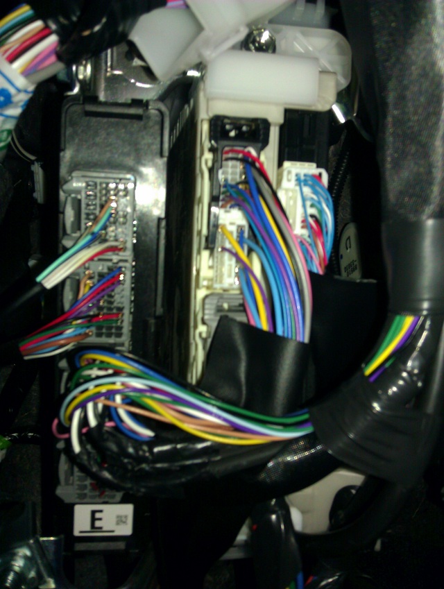
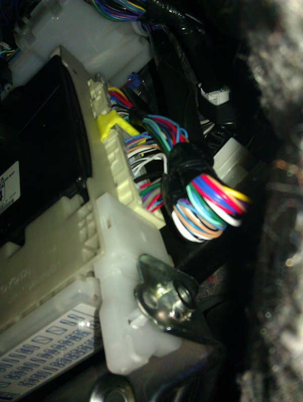
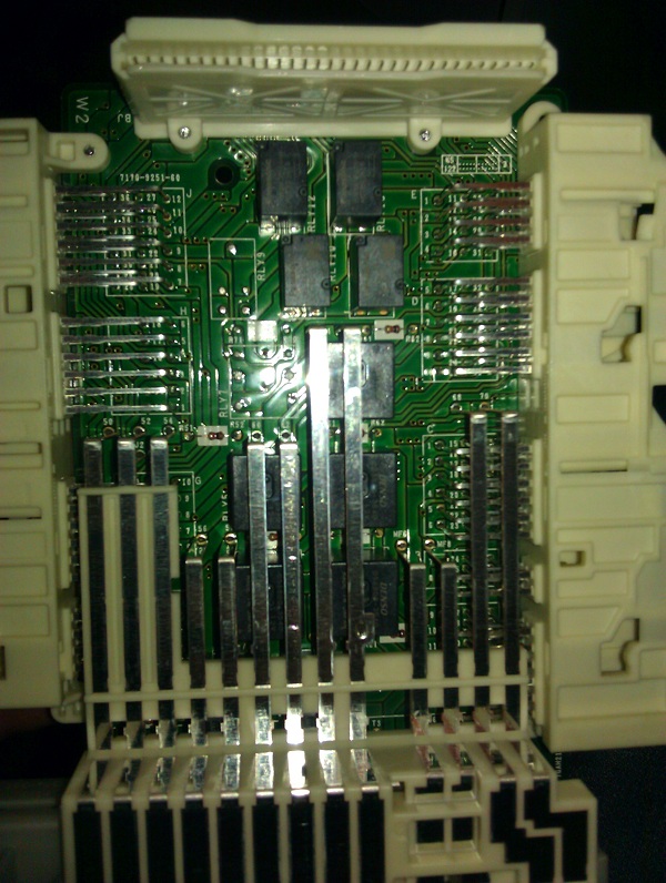
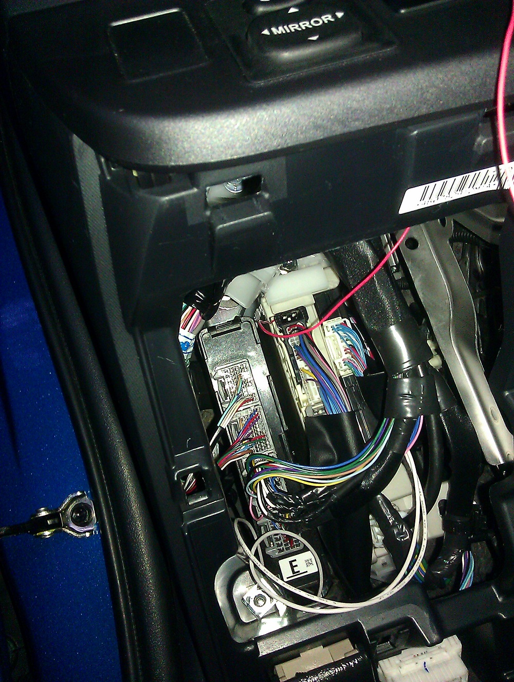
The interior fusebox:
The schematic indicated there might be a fuse, relay, and connectors already in place for foglights. I looked inside and found a foglight fuse, so I decided that I should open the fusebox and solve the mystery.The interior fuse box is pretty easy to remove, open, and modify you just might get a bit cramped getting to it. You need I think 10mm socket, and a mini flathead screwdriver to disengage the tab on the connectors. You will have to remove two 10mm sockets (one might be tricky to get at). You will have to unplug 3 multi pin connectors from the front of the box and the large power connector, 2 many pin connectors from the rear, and likely connectors to the left-wise adjacent computer box that are on the same wire bundle. You need to use a small tool (Screwdriver) to lift the metal locking tab inside each multipin connector. I recall a plastic barbed piece attaching the wire bundles to the box, and a yellow plastic piece obstructing the rear multipin connectors.
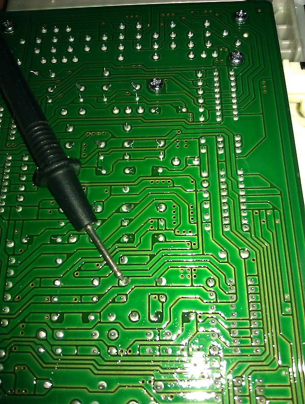
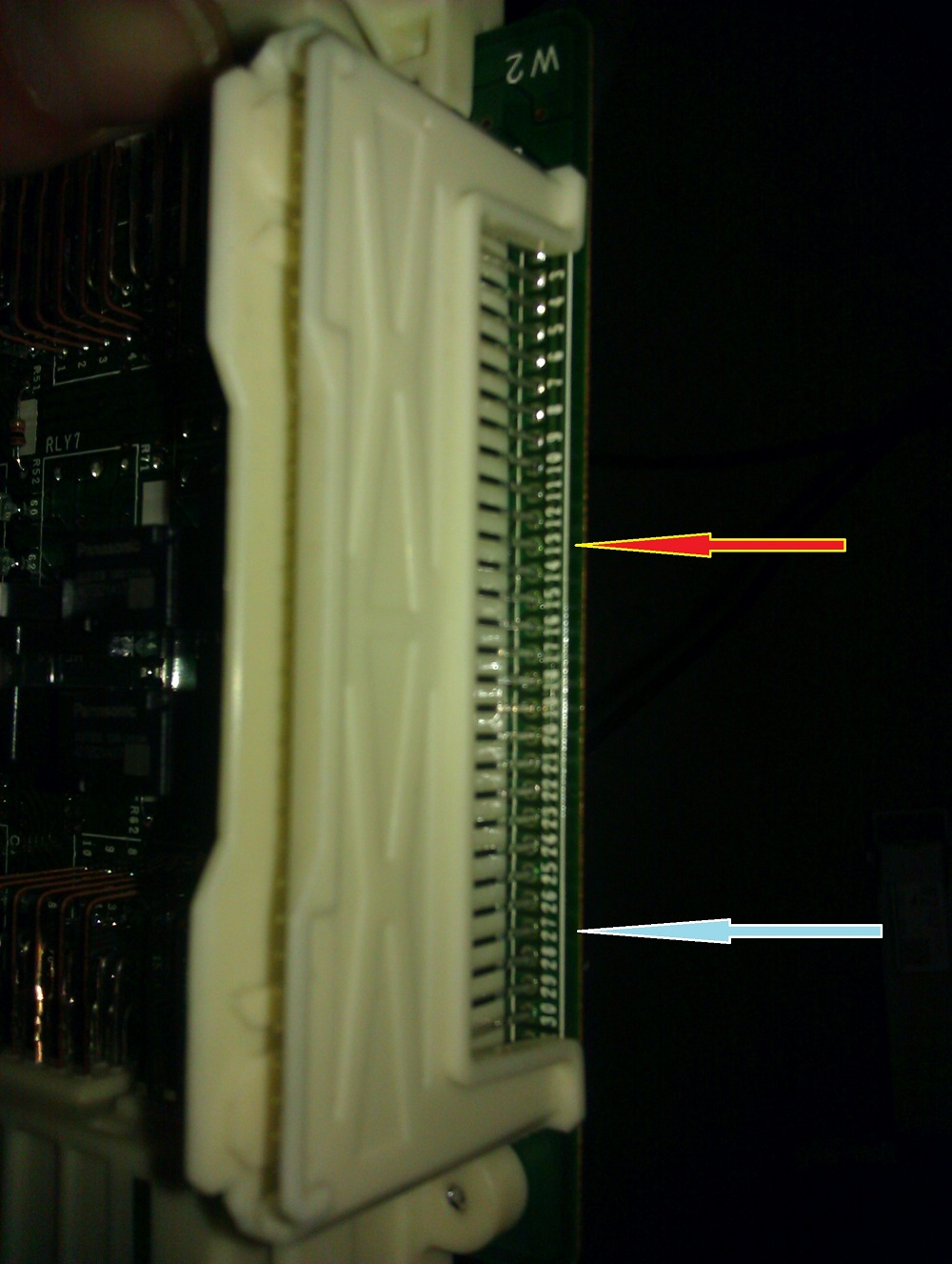
I found that the relay was populated into the fusebox board, and the schematic matched what was inside. The only limiting issue I discovered was that the Main Body ECU did not pull-down the foglight relay (FFGO) when the toggle pin was pulled-down (FFOG). This would be easy to correct, simply bridge pin 13 and 27 together with a wire and soldering iron (red arrow and blue arrow). I decided on one easier since I didn’t have a factory bezel, I would solder a wire to pin 13 to lead to a switch to an easy grounding point. I'm sorry I didn't take more detailed pictures of opening the box.
The box opens up in a few pieces. It requires disengaging small plastic clips (use a screwdriver) for the first cover. You will have to disconnect the black ECU from the relay/fuse-box. You will also have to remove a few small screws on the back of the relay board to remove the relay board from the enclosure.
Wiring the switch wire.
Solder a narrow gauge wire (~20 awg) to pin 13 (red arrow) and route this outside the fusebox and towards your toggle switch. Connect your switch (or bezel) at one end to this lead. On the other end of your switch you should route a wire to ground.
I had discovered pin 7, or the fog light power wire to go to the wiring harness actually had a wire populated in the connector. This wire did not make it to the connector I had found.
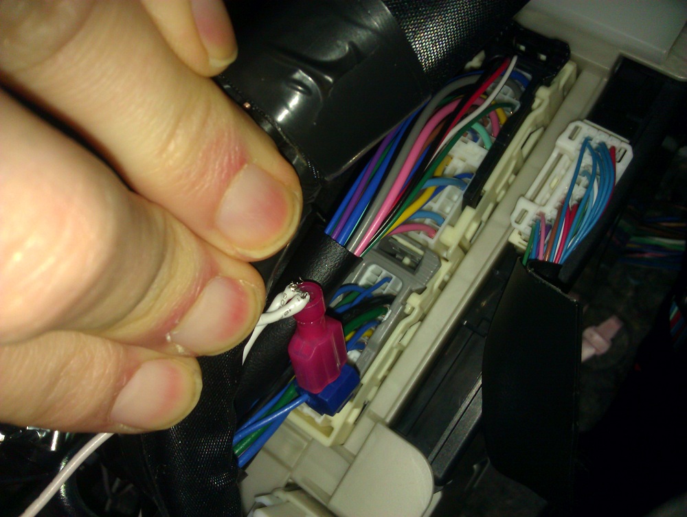
Tap the blue wire that connects to pin 7. This is the third wire down from the top (4th pin down from the top) on the rightmost side. It is a blue wire adjacent to a green and yellow wire. You can now wire this tap to the two taps from the foglight wiring harness we located earlier.
After the wiring was done
Here is my switch I wired up after I was done. I decided I didn't want to by an expensive switch (like in the kit):

Custom Lights
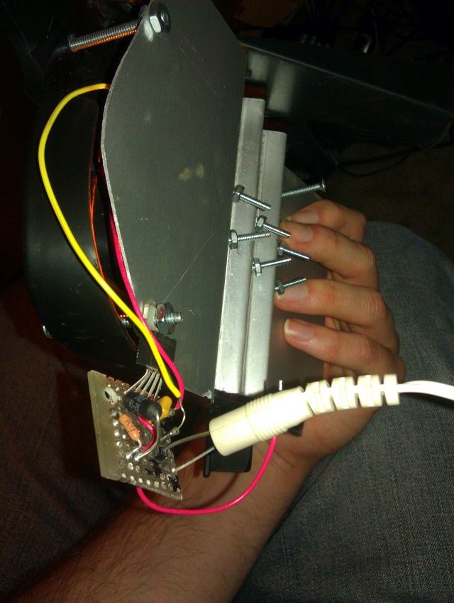
This was the best but most difficult part of the project. I decided on 6 LED’s which turned out to be Amber colored Luxeon Rebels at 130 lumens each. This would provide more luminosity then factory ~19W halogens, and provide less glare with the yellow light. LED’s are really the best option for colored light, as they are generating light at specific wavelengths rather than requiring light reducing filtering.
These high powered surface mount LED’s typically have wide beamwidths, and aren’t suitable for directional light on their own (unlike traditional leaded led’s). I had to also try to fit the fixture on the pre-existing foglight cutout cover. I discovered a 12 degree collimator which turns out to be directional enough to make a fixture that illuminates the road effectively- but doesn’t cause excessive glare to oncoming traffic.
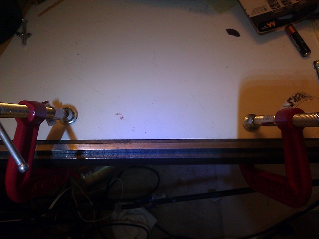
I decided to build my own 700mA led driver. I had to fabricate a metal back plate, to serve as structural support and as a reliable heat sink for the powerful LED’s. I also had to figure out a way to attach everything to the polypropylene plastic. I ended up with a result that was relatively easy to readjust the aiming after being installed.

Ultimately the electronics and optics were sealed with silicone RTV to survive the elements and improve the apperance of the cut plastic.
After installing them I added blinker functionality to deactivate the foglights when the the corresponding blinker came on
Final Results (top)
If anyone finds this interesting, and has any questions or comments you can Contact Me. I may consider building these led fog lights for others if there is an interest.